Automotive Relay Product Guide
Automotive relays come in many shapes and forms. The most basic consisting of an electromagnetic switch.
The term "relay" is sometimes also used to describe small electronic controllers such as glow plug controllers
etc. which also contain electronic circuits
|
Function
|
Typical terminal designation |
Operation |
|
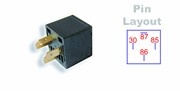
Normally Open 4 pin relay
12v 20A 4 pin relay |
 30 Supply Input
87 Supply Output 85 Coil ground or -ve 86 Coil trigger |
A control circuit between pins 85 & 86 eg, with light duty control switch and wiring , may be used to switch a second circuit with heavier current load via wiring between pins 30 and 87 |
|
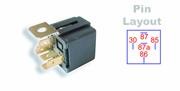
Heavy Duty Automotive Relay
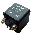 12v
200A relay
12v
200A relay |
30 Supply Input
87 Supply Output 85 Coil ground or -ve 86 Coil trigger |
Normally open relay often used on construction plant for starter circuit control |
|
Double Make & Break
|
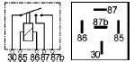 30 Supply Input
87 Supply Output(1) 87b Supply Output(2) 85 Coil ground or -ve 86 Coil trigger |
Similar operation to the standard 4 pin Normally Open relay but has a second terminal in parallel to the output terminal. |
|
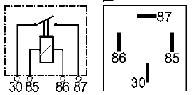
Changeover Relay 5 pin
|
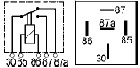 30 Supply Input
87 Supply Output when relay off. 87a Supply Output when relay on. 85 Coil ground or negative. 86 Coil trigger or positive from switch. |
A control circuit
wired to pins 85 & 86 eg, with light duty control switch and wiring , may be used to
relay switching of a second
circuit with heavier current wired to pins 30 and 87
when control circuit is OFF , changing to pins 30 and 87a
when
|
|
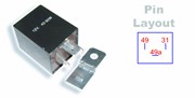
Flasher Relay
SAFU003 direction
indicator relay |
31 Ground or Negative
49 Supply Input battery +ve 49a Supply output to column switch then to indicator lamps. 49b Second output to direction indicator lamps 49c Third output to direction indicator lamps |
The flasher relay or direction indicator relay pulses power to indicator lamps causing to flash on and off at between 60 and 120 flashes per minute in normal operation.
Always check pin position configuration of
relay is correct before fitting |
|
Fuel Pump Relay
|
1 Ignition Coil (negative pulse)
15 Ignition supply from ignition switch 31 Ground or negative 50 Starter motor cranking signal 85 ground for coil may be switched via engine computer. 30 Battery +ve Supply 87 +ve Supply output to fuel pump. Wiring terminal designation may be vehicle specific, consult manufacturers specification. |
The fuel pump relay may supply power to the fuel pump for a couple of seconds to prime fuel system then shuts off until control circuit via engine
control computer grounds coil of relay to switch on again if engine rotation signal is present
from crankshaft position sensor or
distributor pickup.
|
|
Glow plug controller relay |
(L) dashboard preheat warning lamp
Wiring terminal designation may be vehicle specific, consult manufacturers specification. |
The
glow plug controller is typically a timer relay which allows diesel glow plugs to heat up for approx 10 seconds to provide pre heating of
air in the engine pre combustion chambers to allow easier cold starting. May also have post heat functions.
|
|
Time delay relay |
Wiring terminal designation may be vehicle specific, consult manufacturers specification. |
Time delay relays may be used for such applications as wash wipe interval, heated rear window, time delayed motor operation, bus door operation. |