
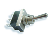
12 Volt DIRECTION INDICATOR FLASHER RELAY RANGE

| Part No | Terminal Layout | Power rating (Watts) | Description | Nett Price GBP | View/Buy link |
|---|---|---|---|---|---|
|
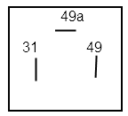 31 : ground
49:Supply 49a:Output |
|
|
tba |
|
|
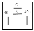
31 : ground 49:Supply 49a:Output |
|
|
tba |
|
|
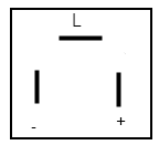 (+)Positive
(-)Negative (L)Load |
|
|
tba |
|
|
 |
|
|
tba |
|
|
 |
|
|
|
|
|
|
|
tba |
||
|
|
|
|
||
|
 ; ; |
|
|
|
Direction Indicator Relay Description
Direction indicators must flash at a rate of 60 to 120 Flashes per minute to comply with UK marking and lighting regulations.
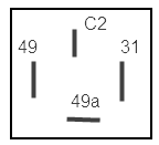
Terminal Designation in accordance with DIN 72 552
31 Common ground return line to Negative battery terminal
49 Supply Input (12v)
49a Output of first turn signal circuit (to indicator switch)
49b Output of second turn signal circuit
49c Output of third turn signal circuit
C First indicator (dash) light
C2 Second indicator (dash) light
Typical Circuit Description
Power is supplied from ignition circuit to terminal 49 of the flasher relay via a fuse.
The output terminal 49a is wired to the centre pole of the turn signal on/off/on switch.
upon activating the direction indicator switch in either direction power is then supplied to the turn signal lamps through the lamp filaments to ground return completing the circuit .
The load of the flasher lamps is sensed by the flasher control unit causing it to switch on / off successively and the turn signal lamps to flash at between 60 and 120 times per minute.
Direction Indicator Faults :
If other lamps flash dimly when indicators circuit is operating
This fault is usually caused by a high resistance to ground return due to bad connection (bad earth faulty ground) on the flasher lamp circuit due to corrosion or poor connection. May also be caused by several other factors such as:
Indicators flash rate too fast
If the indicators flash too fast this may indicate that there is insufficient load on the direction indicator circuit.
Possible cause:
Most vehicles use a 21 watt bulb at each main indicator lamp (front & rear) and a 5 watt bulb at the side repeater lamp.
Direction Indicator Circuit Blows Fuses
If the indicator circuit causes a fuse to blow this usually means the insulation on wiring has become damaged causing a "short to ground".
MoT Inspection of Direction Indicators
A check is carried out for :
Reference : Section 1.4 Mot inspection manual (2012)
Multitimer (modern vehicles)
Late model vehicles may use a "multi timer " unit built into the fuse board
or body control module to operate direction indicators.
The Multi timer often has several other functions related to timed circuits for example
, interior light delay, alarm sounder , reverse bleeper, and windscreen wiper delay.
Seperate relays may also be fitted for each flasher circuit
Diagnostic testing of Indicator Circuit on vehicles with body controller module
Diagnostic equipment with dedicated software can be used to check the direction indicator circuit on some vehicles where a body controller module is fitted.
Diagnostic equipment live data readout of body module may show input signal from turn signal switch ON / OFF function and hazard warning lights switch active function .
Diagnostic equipment Component actuation function can command body control module to operate indicator lamps allowing a quick functional check of lamp operation. Further testing of wiring continuity can be done with multimeter to check for breaks in wiring, short to ground.
Classic Car Indicators
Requirement for direction indicators depends on vehicle first use date.
Vehicles of first use date before 1st January 1936 currently have no legal requirement to be fitted with direction indicators
Vehicles of first use date prior to 1st September 1965 may combine indicators wit stop lamps or front/rear position lamps so front indicator may flash white, rear indicator may flash red.
Vehicles of first use date after 1st April 1986 must have side repeater lamps fitted but these can be incorporated within the front direction indicator lamp if a wrap around lens is fitted so lamp is visible from side.
Semaphore Indicators
Typical part number Lucas SF40 or Lucas SF80
A semaphore arm raises outwards from the side of the vehicle body when direction indicator switch is activated.
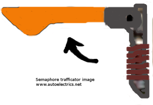
Semaphore indicators (Trafficators) fitted to older classic and vintage vehicles often use an electromagnet to raise each semaphore arm.
Semaphore indicators must also illuminate but do not have to flash. The semaphore indicators can also be wired to allow to flash.
Many classic car owners have additional indicator lamps fitted for road safety and to protect their vehicle.
Typical Direction Indicator Wiring Circuit Colour Codes on Classic British Vehicles
12N trailer wiring colour codes for Direction indicator circuit
Autoelectrics Mobile Products & Services,
Shrewsbury Shropshire
United Kingdom.
Telephone: 01743 884888