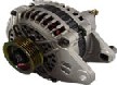
 ALTERNATORS
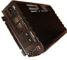 Inverters
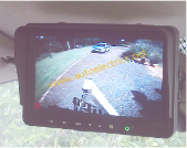 CCTV REVERSING CAMERAS + DVR SYSTEMS
UK Suppliers of Autoelectrical Parts to
Motorists
Motor Trade
Autoelectricians
Garages
Mechanics
Motor Factors
Commercial Vehicle Bodybuilders
Road Haulage Fleets
Hauliers
Passenger Transport
Bus Workshops
Taxi Operators
Farm Workshops
Agricultural Engineers
4x4 Enthusiasts
Construction
Hire Companies
Marine
Special Vehicle Builders
Van Conversion Specialists
System Manufacturers
Autoelectrical Split Charge Relays to Recharge Auxilliary Battery Banks
The autoelectrical terminology 'split charging system' refers to a vehicle wiring installation where the vehicle starter battery is wired to start the engine, and a secondary auxilliary battery receives electrical charging power from the vehicle alternator or generator.
Vehicle Split Charging System Designs
A variety of designs of split charging system exist to enable auxiliary leisure battery charging applications: Suitability will depend on power requirements and full system design.
Alternator / Generator
The vehicle alternator should be sufficiently heavy duty to have spare output capacity. If a split charge system is added to an existing vehicle configuration then alternator and cabling may need to be upgraded.
Battery Capacity
The consumers power requirements is only one factor when considering the number and type of batteries to be fitted to a vehicle. Adding additional batteries increases vehicle weight and fuel consumption. Specific battery chemistry requires matched charging system.
Circuit Protection
Much can be written about vehicle fire risk due to electrical systems.
Any split charging system should incorporate adequate circuit protection to limit risk of short circuit and over load current situations.
Fuses or circuit breakers should be installed close to each battery power source.
Basic Split Charge using a manually operated switch
In the most basic split charge system the Starter battery is linked to the second battery via an on/off switch controlled by the driver. When the split charge switch is on, the second battery is linked to the starter battery allowing charging.
Split charge using an electromagnetic relay
The starter battery is linked to the second battery via the power switch contacts of a relay (terminals 87 and 30). The relay coil circuit (terminals 85 and 86) is controlled by the alternator D+ circuit (excitation signal), so that the coil is energised when the alternator is charging as the engine runs. When the engine is stopped or is cranking during startup, the second battery is isolated from the starter battery.
Voltage Sensitive Relay (VSR)
We can supply or supply and fit voltage sensitive relays (VSR).
A VSR senses the increase in starter battery voltage acheived when the vehicle engine is running and the alternator is charging above a preset value, for example 12.8 volts.
An electromechanical switch inside the relay closes allowing connection of secondary battery bank to the vehicle starter battery which is being charged.
When the vehicle engine is stopped and starter battery voltage drops below a preset value, the VSR contacts open disconnecting the auxilliary battery bank from the charging circuit.
This disconnection is designed to prevent the auxilliary equipment wired to the auxilliary battery bank from draining the vehicle starter battery.
VSR systems may not be suitable for fitment to vehicles with smart alternators or battery management systems
The difficulty encountered with the above systems is controlling the charge current to the secondary batteries.
Battery Isolator Blocking Diode type split charge system
A blocking diode split charge system allows electrical power to flow one way from the vehicle primary battery charging circuit to the secondary battery.
The purpose of the blocking diode is to prevent reverse flow of current from the auxiliary battery to the starter battery
while the engine is being cranked by the starter.
A disadvantage of using a blocking diode is voltage drop between primary and secondary battery systems.
DC-DC Battery to Battery Charger
A DC-DC battery charger controls and limits charging current to secondary battery banks often offering the best solution on modern vehicles where the vehicle is fitted with a 'Smart' alternator.
Maximum Power Point Tracking (MPPT) Controller
MPPT controllers are often installed where solar panels are used as an additional means of charging batteries.