 Autoelectrical Installation and Testing
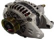 Alternators
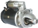 Starter Motors
 Batteries
Vehicle Dynamo Generator
 2023 Dynamo prices from £80 plus carriage part no.HC110483 replacing Lucas LRD101
Vehicle dynamos are generally found as part of the autoelectrical system on older classic and vintage vehicles including classic cars, classic tractors, and vintage lorries with 6 volts (6v), 12 volts (12v), or 24 volts (24v) battery charging systems.
The dynamo is a shunt wound electrical generator. Dynamo electrical power output which rises as engine and armature rpm increases.
Vehicle Dynamos generate electrical power as Direct Current using the Faradays law principle of magnetic induction.
An electrical current is induced in a wire cutting a magnetic field.
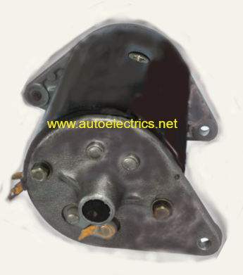
Dynamo Construction
The dynamo consists of a casing with end brackets, a stator with field coils, and armature rotor with commutator.
The dynamo armature rotor is generally driven by pulley via v-belt from the engine crankshaft pulley.
Early dynamos are generally of 3 brush type on 1920s-1930s vintage vehicles such as MG TA and Austin 7.
Later 2 brush type dynamos requiring a seperate external control box are found on many 1950's to 1970's era vehicles.
The Dynamo Stator
Field coils and pole shoes held by screws in an outer yoke casing form the stator.
The pole shoe screws can become extremely tight and may require use of a device such as the crypton pole shoe screwdriver to remove.
Care must be taken to avoid distorting the dynamo yoke (barrel) casing when trying to remove the pole shoe bolts.
Field coils are made of copper wire and lapped with field coil tape.
The F Terminal connects excitation current to the field coils through either a field to battery, or field to ground circuit.
The Dynamo Armature Rotor & Commutator
The armature rotor consists of wound copper windings connected to a commutator.
The armature centre shaft is supported on bushes or bearings.
The commutator acts as a rotary switch in contact with carbon brushes.
Copper bars (segments) soldered to armature wires form the commutator.
Commutator bars are seperated by Mica insulation.
Excessive field current can cause overheating then solder to melt and be thrown from commutator segments.
A worn commutator may need skimming on a lathe and Mica undercutting to restore condition.
Carbon Brushes
Dynamo brushes originally gained their name because metal brushes were used to contact the rotating commutator to allow flow of electricity.
Carbon brushes connect the field coil F via one carbon brush to armature commutator and second brush from commutator to D terminal.
Carbon brushes are held against the commutator by brush springs (brush spring pressure).
Worn brushes can cause dynamo output failure, burning and sparks at the commutator reducing output and eventual commutator failure.
When fitting new brushes these should be bedded to the commutator to improve electrical contact.
Carbon brushes should be free to slide in the brush holders and should make good contact with the commutator.
Brush spring pressure should be equal. Lack of brush spring pressure may cause arcing and commutator damage.
If brushes become jammed and lose contact this can cause the dynamo to stop charging.
Worn dynamo brushes should be replaced.
D Terminal
The Dynamo D terminal provides the power output connection for battery charging via wiring loom and control box.
F Terminal
The Dynamo F terminal provides a circuit connection for generator field excitation current.
Dynamo Field Coils
The dynamo field coils are copper windings insulated with field coil tape.
Dynamo pole shoes mount field coils to the frame or yoke barrel casing of the dynamo.
Countersunk bolts secure pole shoes to the casing frame.
Removal may require use of a pole expander 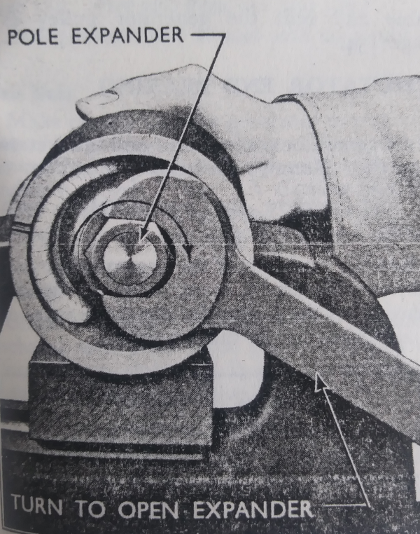
Dynamo types
C35A Dynamo
3 brush 6 volt dynamo. Dynamo output is varied by moving the position of the third brush relative to the two fixed brushes. Field excitation current is controlled by switching through different vehicle circuits to control resistance.
C39 PV/2 Dynamo
19 Amps
C40 Dynamo
4 1/2 inch fan : 20A
5 inch fan : 22 Amp
Field coil resistance : 6 ohms
C40L Dynamo
C42 Dynamo30 Amp
C42 Easidrive Dynamo
35A
C45 PV6 Dynamo
25A
C45 WV4 Dynamo
6 Volt
Application: Bedford
C45 PV6 Easidrive Dynamo
30A
C48 Dynamo
35A
D45 Dynamo
G7 (24 volt) Dynamo
GL4512-11M Dynamo
GL4524-2 Dynamo
GL4524-25 Dynamo
H55 Dynamo
CAV H5512-11 Dynamo
Application : Bedford RL lorry
DO7X Dynamo
Dynamo Voltage Regulator Control Box
A Variety of dynamo control box exist to regulate voltage and current. The regulator should function to allow the vehicle battery to remain at a full state of charge. When the engine is running and battery terminal voltage is lower than dynamo terminal voltage then the regulator should allow battery charging.
Dynamo Checks and Tests
Check condition and tension of generator belt.
Ignition warning lamp (WL) should illuminate with ignition key on and extinguish when the engine is running.
Residual field : Disconnect cables from dynamo , connect voltmeter between D terminal and chassis ground. Engine at approx 1500 rpm , Volt meter reading should be 1 to 3 volts
Dynamo field circuit : Voltmeter connected between D terminal and chassis ground. Ammeter connected between D terminal and F terminal. Increase engine rpm until voltmeter reads nominal system voltage. Ammeter should read aprox 2 amps.
Dynamo armature circuit : Disconnect cables , connect volt meter Black lead to D terminal , Red lead to Earth, run engine 1500rpm , meter reading should be 2 to 4 volts.
Dynamo motoring test : With the fan belt removed, link D & F terminals. With chassis ground connected to yoke frame,
and battery power applied via an ammeter to the D & F link ,
the dynamo should run as a motor.
Voltage Control - Generator trouble
| Symptoms | Probable Fault | Remedy |
|---|---|---|
| Battery in low state of charge. Lacks power when starting Hydrometer reading below 1.200 |
Generator not charging due to: | |
| Broken or loose connection in generator circuit, or regulator not functioning correctly | Examine charging and field circuit wiring. Tighten loose connection or replace broken lead. Examine Battery connections. Repair or renew regulator | |
| Commutator greasy or dirty | Clean with soft cloth moistened in petrol | |
| Giving low or intermittent output when engine running above fast idle | ||
| Generator drive belt slipping | Examie drive belt. Adjust belt tension | |
| Loose or broken connections in generator electrical circuit | Examine charging and field circuits wiring. Tighten loose connections or replace broken lead. Examine battery connections. | |
| Brushes greasy or dirty | Clean with soft rag moistened in petrol | |
| Brushes worn or not fitted correctly | Replace worn brushes and check that brushes bed to commutator correctly. | |
| Regulator not functioning correctly | Have regulator checked by service engineer | |
| Battery overcharged, shown by blown bulbs and frequent need to tup up electrolyte. Hydrometer readings high |
Table adopted from Sunbeam Rapier workshop manual page 41 section N electrical equipment
Flashing the Dynamo
Required to polarise dynamo output either Negative earth or Positive Earth. Remove leads, touch a wire between the dynamo F terminal and battery live terminal.
Dynamo to Alternator Conversion
A range of aftermarket products are available offering bolt on replacement units with similar appearance to the original dynamo but are actually higher output alternator conversions. Increasing current output requires upgrading cable specification.
*Legal disclaimer : Any information on this web page is given in good faith but should not be relied upon as correct. all brands and trade names are respected as property of their legal owner with no association express or implied. By use of this website you accept and understand our terms and conditions which can be read by following the link: Terms