
 Autoelectrical Installation
 Air Conditioning Climate Control
 Alternators
 Starter Motors
 Batteries
Vehicle Diagnostics
Batteries
Vehicle Diagnostics
 Onboard Power
Engine Management
Vehicle CCTV
ABS Brakes
Inverters
Diesel Injection 1
CR Diesel Engine Repair
Diesel Injection Faults
Onboard Power
Engine Management
Vehicle CCTV
ABS Brakes
Inverters
Diesel Injection 1
CR Diesel Engine Repair
Diesel Injection Faults
 HGV Inspection on site
Trailers Towing Equipment
Towing Electrical
Breakdown Assistance
Vehicle Security
Vehicle Alarms
HGV Inspection on site
Trailers Towing Equipment
Towing Electrical
Breakdown Assistance
Vehicle Security
Vehicle Alarms
Vehicle Electrics & Diagnostics Shropshire UK
Vehicle diagnostics Mobile service covering Shrewsbury and local Shropshire and Welshpool Mid Wales areas.
Car and van electrics repair - We provide a mobile auto electrical & mechanical service that comes to you.
Private Customers, Fleet & Motor trade Welcome.
Engine Management warning light on ? Breakdown ? Engine Misfire ? Driveability problems ? Immobilised? Engine Management fault? Electrical fault - Car won't start ? MoT fail Repairs?
Unsure if you should drive the vehicle with a red yellow or amber instrument panel warning light on ?
Active dash warning lights are often an Mot failure.
Autoelectrics Mobile Product Services
Shrewsbury Shropshire
07703 558610

Computerised vehicle diagnostics
Modern cars, vans, trucks, plant and machinery use artificial intelligence (AI) integrated into onboard computer networks forming advanced computer monitoring and control systems.
Computerised control of mechanical systems is intended to aid operation of the vehicle and remove driver error.
Vehicle computer modules process information taken as Inputs from sensors and other connected electronic modules.
Control of mechanical components is via actuator output and feedback.
Problems exist when AI systems go wrong, particularly due to failed sensors, actuators, and wiring connections between components causing no communication faults.
A typical example is the coded key security system where a code is sent from a microchip in a key to computer modules before the vehicle engine is allowed to start. The correct key code or password is required, the key reader (aerial)) must operate, and wiring must be intact to allow transmission of the code message. The code must match the one programmed in the controller computer. There are many potential points of failure which could cause vehicle breakdown.
Many vehicle computer systems are artificially intelligent to the point of knowing a fault exists and alerting the driver via warning lights and messages, but not intelligent enough to detect precise fault location. Fault location becomes the job of the autoelectrician, technician or service engineer.
Cloud based Diagnostics, Vehicle Tracking, Remote Coding and Programming, DOIP
Recent advances in Motor Vehicle technology include cloud based wireless remote diagnostic functions also known as Diagnostics over internet protocol (DOIP)
Messages may be passed as data between a vehicle and the vehicle manufacturer. Messages can also potentially exchange between connected vehicles. Connected vehicle information may for example help to maintain safe stopping distances.
Advancing vehicle AI technology means independent garages are forced to pay software subscription charges to vehicle manufacturers, either directly or indirectly through licensing agreements if keeping up with modern technology is to be enabled.
Vehicle wiring diagrams are constantly changed as vehicles evolve, requiring that only chassis number (vin) related wiring information provides sufficient accuracy to enable effective repairs.
Controller Area Network BUS (CANbus), CAN FD
The Controller Area Bus Network or CAN network allows two way data communication between vehicle electronic computer modules.
Vehicle computers may pass messages on a bus system. In this case the bus system refers to the physical wiring cables between computer controllers. Messages are passed along cables as data often in the form of electrical pulses. The CANbus system has two voltage signal levels: CAN High (CAN-H) and CAN Low (CAN-L). Seperate cables CAN-H and CAN-L form a twisted pair of cables.
CANbus signalling faults occur for many reasons :
Controllers fail,
Controllers are not configured or matched. CAN network configuration coding mismatch introduces faults where one module affects other modules on the vehicle network.
cables become damaged or break causing open circuits or short circuit,
Cables induce spurious electrical currents,
Data messages are not synchronised so crash.
CAN FD refers to a faster system of message communication using Flexible Data.
Vehicle Network Configuration
Vehicle Configuration Test and System (VCATS) engineering is a function often performed by factory auto electricians and engineers at vehicle manufacture. Fitting or removal of computer control modules generally requires VCATS resets of some description to be performed for the vehicle to work properly. Power disconnection / reconnection may require module reset or programming procedures using diagnostic test equipment. Vehicle network communications can send and receive data on different types of systems either optical, wired or wireless.
Instrument Cluster
The Instrument cluster provides guages and warning lamps giving the driver a visual and audio signal of vehicle operating parameters including battery charging , fuelling, ignition, engine rpm, engine oil pressure, coolant temperature,and other funtions.
The Instrument cluster electronics (IKE, EKM) often form an important centralised node on the vehicle computer network connected to many systems whilst holding vehicle specific coding data..
The vehicle instrument panel is fitted with warning lights to alert the driver when a vehicle computer system sees a fault (well, the theory is good !),
in reality, some faults may occur in a split second of time faster than the processing speed of the computer controller.
When a vehicle computer sees a fault and logs certain error codes, it may also trigger a dash panel warning lamp
to illuminate to notify the operator that a fault has been logged.
Instrument cluster electronics are sensitive to battery voltage. Incorrect reference voltages sometimes caused by a faulty battery or charging system or connection may cause intermittent or strange faults with the dash instrument cluster.
Instrument Panel Warning Light On
Dashboard warning lamps illuminated can have numerous causes warning of impending breakdown.
Vehicle manufacturers DO NOT recommend vehicle operation is continued with a warning lamp or warning message active
- It is a warning for a reason !
Dashboard warning lamps may have different function often with a symbol to indicate meaning
and may illuminate Red Orange Amber Yellow Blue Green to signify function.
Vehicle owners manual should specify function
MoT test advisory or fail due to warning light on
Dashboard warning lamp illumination may indicate a fault resulting in MOT test advisory notice or Mot test fail.
(further guidance can be found in the
DVSA MoT inspection manuals
.
Typical operation sequence of vehicle system instrument panel warning lamp is to illuminate when the key is switched to ignition position as a vehicle system self check is carried out, then should go off when system self check is passed and the vehicle engine is running.
Vehicle Safety Features
Vehicle system control unit software safety features check logged fault codes which may in some cases prevent functionality and cause breakdown :
For example a vehicle self protection feature could stop the engine running when a low fuel pressure fault code
has been logged to prevent fuel leakage which may cause fire.
Vehicle Fault Codes
Much can be said about vehicle fault codes this is a link to more information.
A fault code may be logged in vehicle computer contrl unit memory if an error is detected.
Vehicle fault codes often identify that a sensor, actuator, or componenent is not working correctly.
Much of the problem with computerised vehicle diagnostics, fault codes and descriptions found on scan tools during vehicle checks, rests with interpretation of vehicle manufacturers software engineer's cryptic technical terminology (fault codes) in to plain English which can be understood firstly by the technician in vehicle workshops, and secondly, perhaps, more importantly, by the customer who will be paying for the vehicle repair work and is faced with the decision of evaluating costs and benefits of repair versus vehicle replacement.
Open Circuit
A vehicle fault code may log as an open circuit fault if a component is disconnected, unplugged, or there is broken wiring.
The fault code may log as open circuit but will not identify the exact location of a break in wiring etc.
Short circuit
A vehicle fault code may log as a short circuit to ground, or short circuit to power (B+), again this identifies a problem in the circuit but will not divulge location.
Component fault code
A fault code related to operation of a specific component again does not mean that unit is faulty. Fault codes for DPF soot accumulation can be caused by broken wiring to pressure sensors.
Retrieval of vehicle fault codes
Many vehicles require computerised diagnostic equipment with dedicated software to interrogate electronic system control modules and retrieve stored fault codes.
Automotive system electrical diagnostics involves an interrogation scan of the vehicle computer for stored fault codes using suitable diagnostic equipment such as a Mobile Diagnostic Computer (MoDIC), Mobile Diagnostic Interface System (MoDis) or scan tool fault code reader.
Some older vehicles (usually Japanese) have a self diagnosis function allowing the the fault code to be read by counting the flashes of the check engine light and looking up the value in a reference table. Commercial vehicles, Construction and Agricultural machines may display fault codes on a diagnostic screen but require engineer user code to access.
Read / Delete Vehicle Fault Codes
Fault Code Categories
Historical fault codes
Intermittent faults which occur during driving may be logged as a fault code in vehicle computer memory.
A dashboard warning light may illuminate to advise the driver an error has been detected.
Several error codes may be present due to accumulation over time.
Component Disconnection - Open Circuit Fault
Warning: Avoid trial and error random disconnection of vehicle electrical connectors unless you have equipment to reset fault codes.
Trial and error component disconnection may cause fault codes to be logged in control unit memory then requiring diagnostic equipment plug in to clear false fault codes.
Once a vehicle electronic control module has logged certain fault codes this may prevent engine starting or cause erratic running until an adaptive system relearns parameters.
Warning: Disconnection of piezo type diesel fuel injectors whilst the engine is running can be dangerous and introduce further problems such as leaving the injector open causing fuel build up in combustion chamber and potential hydraulic damage.
Vehicle Control Unit Memory Reset
Diagnostic equipment will reset the vehicle computer control system software to turn a warning light off,
however
Warning: If a vehicle fault is still present the check light will often illuminate again once a driving cycle has been completed unless the fault has been rectified.
No Stored Fault Codes ?
No stored fault codes may result where a vehicle fault or glitch happens too fast for the control unit software to register.
Explained by the instructor of a Bosch engine management training course as : Imagine a photographer taking pictures of a racing car going around a track at high speed,
if the shutter speed on the camera is set incorrect or photographer too slow,the car may pass by without any picture being taken.
Vehicle faults may happen fast, particularly sensor faults.
Fault detection may involve use of an oscilloscope to data log the vehicle during operation hoping that the fault will reoccur during testing. Intermittent faults can be both time consuming and expensive to locate.
Vehicle Diagnostic Test - Electronic Health Scan
Vehicle diagnostic equipment is capable of
- Fault code reading
- Actuator testing Actuator testing can verify wiring circuits by operating the suspected faulty component on a wide range of vehicle systems. The actuator test function can allow some components to be thoroughly cleaned which may save replacement cost.
- Programming and Coding Some components such as electronic fuel injectors , throttle bodies etc may need adaptation coding to the vehicle ecu.
- Advanced Oscilloscope Electronic System Testing Electronic signal testing using an Oscilloscope can be carried out when indepth diagnostics are required. Once described by a customer "e; as the difference between a doctor and a surgeon "e;
Vehicle Repair
Following auto electrical or mechanical diagnostic testing, a faulty wiring circuit may be repaired or component adjusted , cleaned or replaced.
Vehicle ECU Memory Reset Procedures
Following repair work the fault code memory of the vehicle computer may need to be reset to clear any stored fault codes.

Check Engine lamp
Check Engine Control Unit (ECU) / Emissions / Engine management warning / Management Information Lamp ( MIL ) / Powertrain Control Module (PCM) lamp
illumination indicates that the vehicle engine management computer control module has identified a fault related to the efficient
running of the engine and possibly affecting exhaust gas emissions.
Vehicles with diesel engines may use the glow plug pre heat warning lamp to indicate engine management fault information.
If the check engine warning light illuminates during engine operation then a fault code has almost certainly been logged by the engine control system.
Limp Home Mode
Fault detection may cause the engine warning lamp on with engine control unit strategy to reduce engine power output by reverting to limp home or restricted mode as a safety feature to protect the engine or environment.
Limp home mode is usually be noticed by the driver because of
Potential ECM warning light on causes
Sensor Inputs and Outputs :
The expected value from each engine sensor is programmed into the software of the engine control module as a parameter on a lookup table referred to as a map. (Fuel map, Ignition map, etc).
An out of range parameter value may represent a faulty component , wiring circuit or mechanical condition.
The check engine lamp may illuminate to notify the driver that a fault has been detected where a value exceeds parameters programmed in to engine controller memory map. Sometimes faults may store without warning light operation.
Actuator Inputs and Outputs
Electromechanical actuators are used to position components.
Engine Sensors, Actuators , and Common Faults
Advanced technology has added lots of control measures to basic combustion engines to increase fuel economy and output power whilst reducing exhaust pollutant emission.
Engine position sensors :
Cam position sensor
Function: Camshaft position sensor(s) are used to identify cylinder phasing
Crankshaft (CKP)position sensor
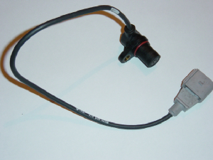
Function : Identification of engine crankshaft position and calculation of engine speed and combustion forces.
Frequency and amplitude of signal is proportional to engine rotational speed.
Camshaft and CKP failure Symptoms: Non Start, Misfire
Typical failure : Signal errors can occur due to sensor failure , phonic wheel damage, loose component, wiring connection failure, loss of synchronisation between crankshaft and camshaft(s).
Driver Input Sensors
Throttle position sensor (TPS) / Accelerator Position sensor (APP)
Function: Driver demand signal. TPS failure may occur due to wear of potentiometer track causing flat spots and hesitation when accelerating.
Brake pedal position & Clutch pedal position sensors
Function :Used to reduce or stabilise idle speed and fuel delivery quantity when engine is off load.
Fault symptoms : Worn out switches may result in false (implausible) signals.
May affect truck mounted pto driven mobile equipment operation.
Engine Temperature and Load Sensors
Mass Air Flow (MAF) sensor
MAF sensor measures volume of air entering air intake.
Air Mass Meter measures weight of air entering intake tract.
Engine load sensor which can effect fuel metering (petrol engine) or EGR position (diesel engines) .
Fault code P0100 may relate to an air flow fault which could be identified as a
faulty air flow sensor or incorrect flow of air past a good sensor for whatever reason eg broke wiring.
Intake Air Temperature Sensor (IAT)
IAT may be incorporated with air mass meter , with MAP sensor (T-MAP) or seperate.
Manifold Absolute Pressure Sensor (MAP)
MAP sensor measures engine load by vacuum (petrol engines) or boost pressure (turbocharged engines) at intake manifold.
Faults: Split or blocked pipes can effect operation.
MAP signal can influence fuel control, EGR, and turbo boost.
Temperature Sensors
Engine temperature measurements may be signalled by either
negative temperature coefficient (NTC) or positive temperature coefficient (PTC) engine coolant temperature (ECT) sensor
or cylinder head temperature (CHT) sensor out of range eg engine overheated.
Temperature signal is processed to compensate fuel injection delivery,
egr position and diesel preheat functions to give engine smooth running.
Overheating may cause an engine to sieze.
Coolant warning lamp
Low coolant level. Check for leaks as engine damage may occur due to loss of coolant. A red low coolant level warning lamp may also illuminate if the wiring is chaffed and shorted to ground or the level sensor is faulty.
Temperature warning lamp
Indicates a problem with the engine cooling system which may cause engine damage. Possibilities are ; blocked radiator , faulty pressure cap, coolant leaks, combustion gas leak into cooling system, cooling fans not operatng due to motor ,switch,or wiring defects.
Engine Fuel Delivery System
Low and high pressure fuel injection pumps, fuel pressure regulator, fuel injectors.
Fuel systems are prone to faults caused by fuel contamination such as mixing petrol and diesel fuel when refuelling , and general wear.
Diesel Common Rail Fuel Pressure Fault
Modern diesel engines fitted with common rail fuel systems which operate at very high fuel injection pressures may log a fault code when a deviation in actual and desired fuel pressure is present indicating potential fuel leakage.
Turbocharger Boost pressure control :
Turbocharger waste gate position and hence boost pressure control is often actuated by electromechanical solenoids
controlling vacuum circuits.
Common faults may include: Worn turbocharger, seized or jammed wastegate,
Turbo boost pressure solenoid loss of vacuum due to vacuum pump wear, split or blocked vacuum pipes, electrical
circuit faults with control, solenoid or wiring, mechanical faults.
Lubrication
Oil Pressure warning lamp
Illumination of a red oil pressure warning lamp indicates low engine oil pressure which may lead to major engine mechanical failure ie engine seizure
and breakdown.
Possible causes: Low engine oil level, oil pressure switch or circuit fault, Oil pump failure, Oil pressure relief valve fault.
Oil level warning lamp
Certain vehicles are fitted with a red yellow or amber low engine oil warning lamp on the dash and an oil level sensor in the engine sump.
Oil Service Light
Oil service light may come on to advise an oil service is due.
Oil service frequency data calculation may be programmable. Oil service light reset may require manufacturers procedure
or diagnostic tester.
Exhaust System
Lambda Sensor
Petrol Engine Lambda Sensor
Lambda sensors detect the oxygen content of exhaust gas and are used as a feedback signal to the engine control computer
for control of fuelling.
Lambda sensors can deteriorate due to age or contamination which may cause slow switching resulting in high exhaust CO emissions
due to incorrect fuelling leading to driveability problems or Mot emissions test failure.
Lambda sensor fault codes may also relate to problems other than the sensor itself.
Heated Exhaust Gas Oxygen HEGO 4 wire Lambda sensor
The Lambda sensor features a heater circuit. Lambda sensor operation is affected by sensor temperature .
Lambda sensor feedback signal is only used when engine operating temperature is sufficient to enable
closed loop control status.
A second lambda sensor may be fitted in the exhaust system after the catalytic
convertor to monitor condition of the exhaust catalyst.
We supply a range of replacement engine sensors and actuators at competitive prices
Exhaust Gas Recirculation (EGR)
EGR systems function to reduce combustion temperature and oxides of Nitrogen (Note : not Nitrous oxide !).
EGR and Idle speed control ( ISC ) devices are particularly prone to blockage and failure due
to build up of carbon and soot deposits which can restrict the air inlet system of the engine.
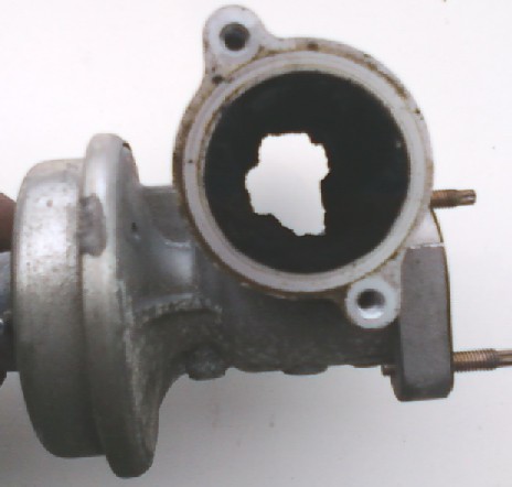
EGR systems may cause the MIL warning lamp to illuminate intermittently and flag a P0400 EOBD
fault code due to "critical system malfunction" as described on certain diagnostic equipment!
Exhaust additive systems & Diesel particulate filters
Exhaust additive systems introduce chemicals in to the exhaust system to reduce diesel soot emissions by passing gases through a Diesel pariculate filter (Dpf). Many of the additives are Urea based and corrosive. Typical faults include damage to wiring from leaking additive.
If failure of an exhaust additive system occurs the likely knock on effect is soot and carbon build up inside the diesel particulate filter.
Dpf blockage may occur over time causing the vehicle software to activate a limp home mode function causing power restriction.
Dpf regeneration is a process where control sofware monitors engine temperature causes the engine to run in a programmed sequence to attempt burn off of excessive carbon and clear the system restriction.
DPF regeneration is not always possible and may require specialist cleaning of the dpf filter or dpf renewal.
Exhaust Brake
Exhaust brakes are fitted to hgv commercials comprising a butterfly flap in the exhaust system.
Flap closes to provide additional engine braking by restricting flow of exhaust gas.
Vehicle Speed Sensor (VSS)
PO720 gearbox output shaft speed sensor fault may cause the speedometer to stop working.
Anti-theft Immobiliser warning lamp
Typically illuminates or flashes red whilst the vehicle immobiliser is active preventing engine start.
OE manufacturer immobiliser systems are often integrated into several vehicle on board computer systems and may prevent starting, ignition, or fuelling circuits from operating.
Faults can sometimes occur if a receiver does not recognise the signal transmitted by a coded key or remote,
or no transmission due to defective remote/discharged battery, or broken wiring causing CAN signal faults.
In the event of breakdown OE factory immobiliser systems can rarely be bypassed other than by reprogramming.
Aftermarket alarm and immobiliser systems are installed as an added security measure by some owners.
If aftermarket immobiliser systems fail they can normally be removed or bypassed by an autoelectrician to enable vehicle operation.
Warning: You should check with your vehicle insurance company if an aftermarket alarm is to be removed as this may affect insurance policy validation.
There is more information about alarms & immobilisers on our vehicle security page.
Computerised Diagnostics
Modern Diagnostic equipment with up to date software for modern vehicles is one of a range of tools providing Electronic Health Scan, Fault code reading, Fault code clearing, Actuator tests, ECU interrogation for live data.
Vehicle Diagnostic testing available in Shrewsbury Oswestry Telford Shropshire & Welshpool Mid Wales areas.
Vehicle Diagnostic Software for Cars Vans Trucks and Tractors includes
European EOBD American OBD2 and Manufacturer Specific Car Van Protocol and Truck/ Agricultural SAEJ1939 Protocol
Ford
Landrover with Ford TDCi engine
Rover Mini MG Rangerover LDV
French Cars and Vans : Citroen Peugeot Renault
Italian Cars Vans Trucks : Alfa Romeo Fiat Iveco Lancia
German Cars vans and Trucks : BMW Mini Mercedes Benz Porsche VAG Audi Bentley Seat Skoda VW Volkswagen
GM Cars and Vans Opel Saab Vauxhall
Jeep Chrysler
Japanese Cars and Vans : Daewoo Daihatsu Honda Hyundai Isuzu Kia Mazda Mitsubishi Nissan Proton Subaru Suzuki Toyota
Volvo
Eberspacher and Webasto specialist diagnostic equipment.
Manufacturer Systems include : Ford,Bosch, Sagem, Renix, Delco, Denso, Autoliv, Lucas,
Vehicle System function diagnostics for :
Common Rail Diesel, Engine Management,
Petrol Fuel Injection,Diesel Fuel Injection including Lucas EPIC,Spark Ignition,
Antilock Braking system (ABS), Airbag,Adaptive damping,Air conditioning, climate control,Audio control,Cellphone, Central
door locking,Diesel pump electronics,Immobiliser,Insrument cluster, Dashboard,Lighting control, CANbus,Passive Antitheft PATS,Power
doors, Steering Control, Electrically operated power steering, parking sensors, tyre pressure monitoring control, ECU information
& coding. DPF regeneration.
Breakdown callout and diagnostics in Shrewsbury, Telford ,Shropshire areas.
![]()
Battery Charging system warning lamp
Red battery charge warning light on indicates that either battery voltage is out of range or that the alternator is not generating current to recharge the battery.
Low battery voltage can be caused by many faults, for example :
Incorrect battery fitted to a vehicle with alternator smart charge system,
A faulty battery with shorted cell
Faulty alternator / generator / dynamo or charging system components or wiring.
Insecure generator or loose / broken drive belt
Battery discharge fault.
Fuseboard or circuit board faults caused by dry soldered joints, blown diodes or corrosion
Electronic control module faults
Incorrect battery reference voltage Vset levels may affect engine management computer, and other electronic control systems sometimes causing relays to 'click' rapidly.
Our mobile service can verify the condition of your vehicle battery using either midtronics or Bosch battery tester,
check for alternator current and voltage output, diode condition ,and trace wiring faults which may be causing the alternator not to charge or the battery voltage to drop.
Systems on many vehicles are often computer controlled and sensitive to battery voltage levels which may set a fault code requiring dedicated test equipment to reset or battery match.
Low battery voltage can occur due to current drain by either something left switched on or by faulty circuitry which may cause for example a vehicle battery to drain overnight.
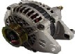
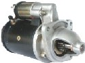
Component Supply
We supply an extensive range of Rotating Electrics : Alternators , Starter motors and vehicle electrical components
We have Alternator Dynamo and Starter Motor unit repair and recondition facilities
We have a bench test facility to free run bench test your alternator.
Airbag or Supplementary Restraint system (SRS) warning lamp
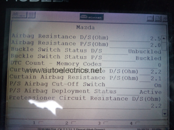
An Airbag warning light staying on signals a fault categorised as a Major MoT test failure (Mot testers manual 7.1.6).
SRS Warning Illuminates if a fault is recognised by the airbag control module.
Airbag deployment is controlled by sensors which react to impact above 20mph.
The SRS system self checks for wiring, sensor ,and actuator faults which may cause false triggering.
If a fault logs in srs control unit memory, the system normally disables and illuminates an airbag failure warning lamp on the dash panel.
Faults causing illumination of the airbag warning light can occur due to wiring, connections, impact sensors, control module faults, igniter defective, spiral cable defective, abnormal system voltage.
Airbag systems have a self check diagnosis function which logs srs fault codes if an error occurs.
Diagnosis is by interrogation procedure with suitable computerised diagnostic equipment.
Live data from the scantool shows status and electrical readings from Safety Restraint System (SRS) Components.
In the event of a crash, airbags may deploy to protect occupants.
Airbag deployment will often cause crash data to be stored in the airbag module.
Please note we do not clear crash data or repair airbag control modules for liability reasons.
We have diagnostic facilities for airbag fault code retrieval, replacement component fitting,
and post repair clearing of airbag system fault codes.
Brakes
Anti-Lock Braking System (ABS) / Electronic Braking System (EBS) warning lamp
Antilock braking system faults may cause an ABS light ,traction control system (tcs) light or skid symbol,
to stay on or flash incorrect sequence. ABS warning lamp on or showing system malfunction causes MoT test fail (MoT testers manual s1.6).
Antilock braking operates by rapidly applying, and releasing the brake on each wheel just before it locks.
When the ABS system logs a fault this may cause the ABS to disable with affects on braking and steering control
requiring increased pedal pressure as the system reverts to failsafe mode.
Typical reasons for ABS light illumination are ; faulty wheel speed sensors, damaged or dirty rotor
sensor ring, faulty modulator solenoids, abnormal battery voltage, system pressure faults, wiring faults.
Fault code reading using diagnostic equipment, possibly followed by individual component
oscilloscope signal testing or wiring checks then repair.
Brake fluid level warning
Brake fluid level warning lamp takes its signal from brake fluid level reservoir switch.
Illumination may indicate loss of brake hydraulic fluid and brakes or esnsor wiring or brake sensor failure.
Brake pad or lining wear light on
Check condition of brake pads or shoes.
Faults in brake pad warning sensor wiring circuit may also cause brake sensor warning lamp to illuminate
and potential braking system failure.
Steering
Electronic Power Steering (EPS)
Steering electronics often require recalibration of steering angle sensor after battery disconnection or replacement.
EPS warning lamp is usually red or yellow or a steering wheel symbol
Vehicle Lighting
Bulb failure warning
May illuminate if an exterior bulb is out or incorrect wattage fitted.
If fitting vehicle bulbs check correct bulb type, voltage and wattage is used.
Indicator Warning Lamp
Indicator turn signal warn light on dash should flash if left or right turn signal applied.
Indicator faster than normal flash or green flasher light permanently on usually indicates a bulb not working
or circuit fault.
Vehicle Diagnostic Training & CPD
Automotive diagnostics involves more than plugging in a scan tool to read faults.
Computer diagnostic error codes only provide a clue as to what the control system
recognises as a fault but remember it is an electro mechanical system which is under repair.
Training providers often refer to "Cause" and "Effect" when lecturing on automotive
diagnostics.
Extensive Motor trade experience combined with continuing professional development (CPD) of staff through manufacturer system training courses aids vehicle system diagnosis & repair.
Vehicle Diagnostic Equipment Sales
Extensive use of vehicle diagnostic equipment in the course of business has enabled us to gain links
with reputable suppliers of vehicle diagnostic equipment for Car Van Truck and Agricultural equipment markets.
If you are a trade customer looking to purchase such equipment or manufacturer seeking a distributor please feel free to enquire.
Professional level diagnostic equipment is often expensive and cost of such equipment can
easily run into several thousands of pounds.
If purchasing diagnostic equipment we recommend reviewing not only initial purchase price
but also the ongoing cost of software updates and service contracts to enable continued operation on modern
vehicles. Access to technical information such as wiring diagrams , component locations, and coding information is
often available by subscription to vehicle manufacturers website.
Car diagnostic testing in Shrewsbury Oswestry Telford Shropshire & Welshpool Mid Wales areas . Call 07703 558610 to book.
Automotive Diagnostics supplied to * Private Customers * Motor Traders and Garages * HGV and Light Commercial vans * Road Haulage Fleets * Passenger Transport Taxi Bus